CALL US TODAY
0410 655 648CALL US TODAY
0410 655 648
Installing ducted air conditioning in Wollongong involves more than selecting a system with enough heating and cooling capacity. The amount of usable roof space can determine whether installation is practical, where the indoor unit can be positioned and how efficiently air can be distributed throughout the property.
Roof-cavity height, structural framing, insulation, existing services and access all influence the design. When these factors are assessed properly, the system is better positioned to provide balanced airflow, quieter operation and efficient performance.
Ben Air Conditioning helps Wollongong property owners assess whether their roof space is suitable for a ducted system. This includes checking equipment clearances, duct routes, service access and potential obstacles before the installation design is finalised.
The roof cavity is more than a convenient place to conceal equipment. It usually contains the indoor fan coil unit, insulated ductwork, return-air components, zone controls and connections to ceiling outlets.
There is no universal minimum roof-space height that suits every ducted air conditioning system. The space required depends on factors such as:
A cavity may appear large when viewed through a ceiling manhole but still provide limited usable space once trusses, bracing, insulation and safe access requirements are considered.
A system that technically fits may also perform poorly if the ductwork must be compressed, sharply bent or routed through narrow openings. A detailed site inspection is therefore important before the equipment and installation layout are confirmed.
The indoor fan coil unit is generally the largest individual component installed inside the roof cavity. It must be positioned securely and level, with enough room for connections and future maintenance.
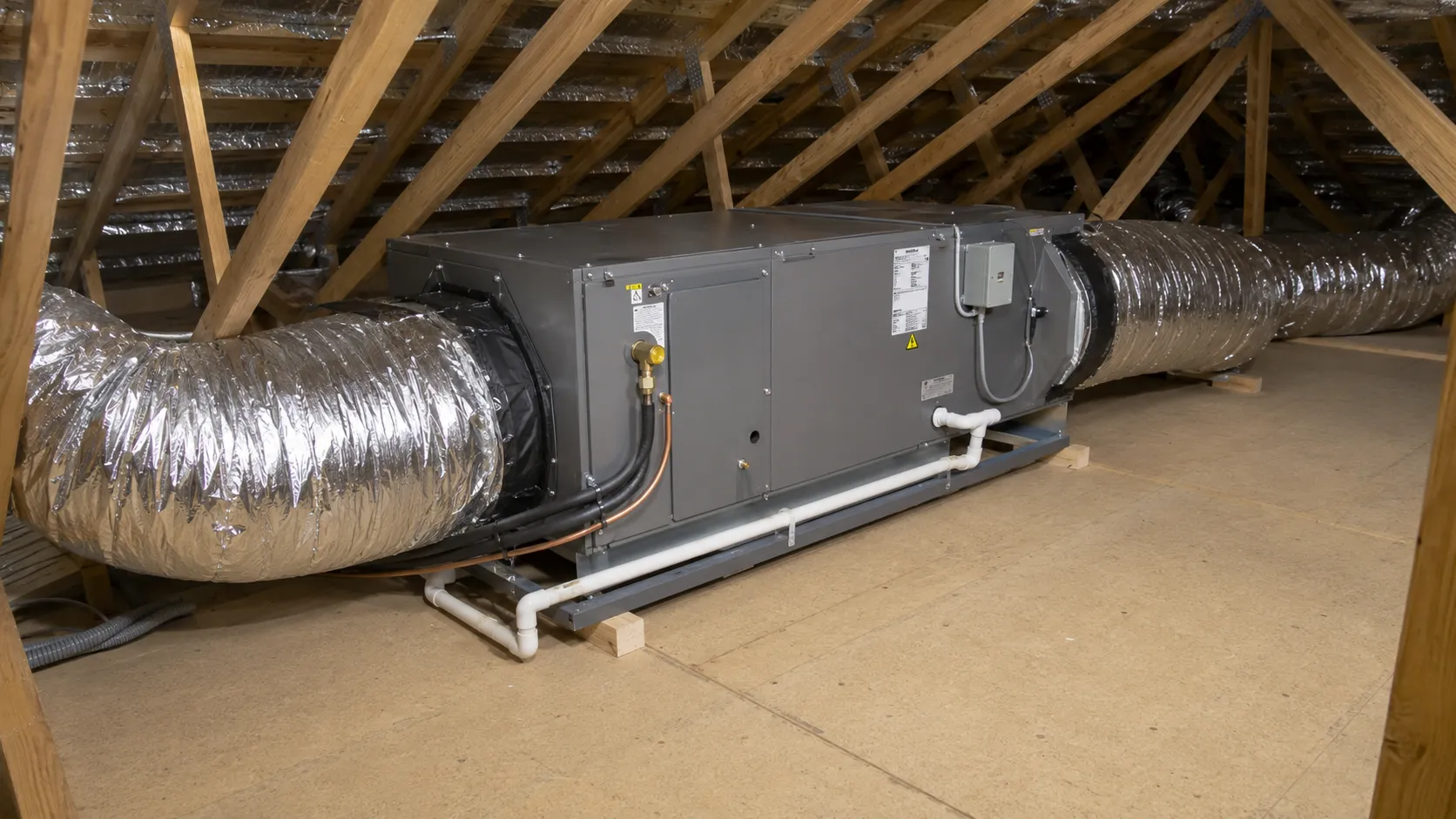
Adequate space is needed to:
The installer must also be able to move the unit through the roof-access opening or another suitable entry point. A unit that fits within the cavity may still be unsuitable if it cannot be safely moved into position.
Ductwork also requires more space than its internal diameter alone. Flexible ducts are surrounded by insulation and an outer protective layer, all of which must remain intact and uncompressed.
Tight bends, flattened sections and restricted connections increase airflow resistance. This can reduce delivered capacity, create noisy outlets and cause rooms furthest from the indoor unit to receive insufficient conditioned air.
Ducted systems rely on large volumes of air moving through properly sized supply and return-air pathways. The roof cavity affects how directly these ducts can be routed and whether they can retain their full diameter.
Restricted roof space may result in:
Each restriction increases static pressure within the system. If the duct layout is not designed correctly, the fan must work harder to move air, potentially increasing noise and energy use.
Where space is limited, the duct sizes, fan settings and overall distribution design should be reassessed rather than simply forcing standard ductwork into the cavity. Any compact or alternative ducting solution should be suitable for the selected system and supported by the manufacturer’s installation requirements.
Unconditioned roof cavities can experience substantial temperature extremes, particularly during hot Wollongong summers and cooler winter conditions. Duct insulation helps protect conditioned air as it travels between the indoor unit and each room.
Where sufficient space is available, ducts can be:
In a cramped cavity, duct insulation may become compressed against framing or roofing materials. Compressed insulation provides less thermal protection, allowing cooled air to gain heat in summer or heated air to lose warmth in winter.
The ductwork should also be properly supported. Unsupported flexible ducts may sag between fixing points, creating additional resistance and reducing airflow.
Adequate space therefore contributes to both thermal performance and the long-term reliability of the system.
A ducted system uses the roof cavity as its primary service area. The available space must accommodate several components rather than only the indoor unit.
The indoor fan coil contains the fan and the heating or cooling coil. Its dimensions vary according to the manufacturer, model and system capacity.
Clearance may be required for:
There should be enough room to access service panels without dismantling roof framing or damaging surrounding ductwork.
The indoor unit should not be squeezed tightly between rafters, trusses or insulation. Where the proposed location is difficult to reach, another position or a more compact unit may provide a better long-term result.
The main supply duct carries conditioned air away from the indoor unit. Smaller branch ducts then distribute the air to individual rooms or zones.
Main ducts need sufficient space to:
Branch ducts need clear pathways to each ceiling outlet. Structural framing, plumbing, electrical cables, exhaust ducts and other roof services can limit the available routes.
The return-air pathway also occupies significant space. It must be large enough to deliver the required air volume back to the indoor unit without excessive restriction, whistling or fan noise.
Each ceiling outlet connects to a plenum box within the roof cavity. The plenum and duct connection must fit above the ceiling without interfering with joists, beams, downlights or insulation.
A zoned ducted system may also require room for:
The available space can therefore affect the number and arrangement of zones. Zoning should be designed as part of the overall airflow system and should not be treated as a solution for restrictive or undersized ductwork.
Roof cavities can appear generous on building plans but become difficult to use once framing, insulation and existing services are considered.
A shallow roof pitch reduces the vertical clearance available for the indoor unit and ductwork.
The cavity may have sufficient total volume but still lack enough height in the areas where the equipment needs to be positioned. Flexible ducts can become compressed between the ceiling and roof materials, particularly near external walls.
Flat and skillion roofs are often more challenging because they provide a narrow service zone shared with insulation, cabling and structural supports.
Possible responses may include:
System capacity should not be reduced simply to make the equipment fit. A correctly sized system should be selected according to the property’s heating and cooling needs rather than simply choosing equipment that fits the available cavity. The selected system must still meet the property’s calculated heating and cooling requirements.
Timber roof trusses commonly contain diagonal webs that restrict the pathways available for ductwork. These structural members should not be cut, drilled or altered without appropriate professional assessment and approval.
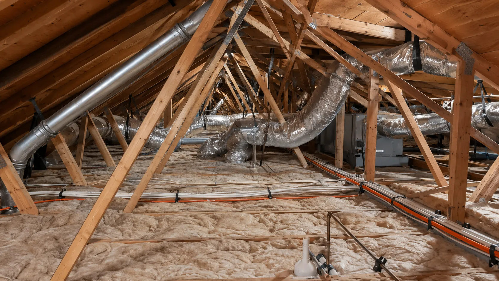
Other obstacles may include:
Duct routes should work around these fixed elements without being sharply bent or compressed.
If structural alterations appear necessary, advice from a suitably qualified builder or structural engineer may be required. An air conditioning installer can identify potential support locations and obvious constraints, but formal structural capacity should not be assumed where there is uncertainty.
Ceiling insulation can take up a substantial amount of vertical space and may conceal joists, electrical cables and other hazards.
Laying ducts directly on top of deep insulation may push them against the roof material. Moving or compressing insulation can also reduce the thermal performance of the ceiling.
The installation should avoid unnecessary disturbance to insulation and should maintain the required clearance around electrical equipment, downlights and other heat-producing components.
Ducts may need to be suspended or supported above the insulation where practical. Any displaced insulation should be reinstated correctly after the work is completed.
Roof access must be considered both for installation and future servicing.
The installer will assess:
A system should not be placed in a location that cannot be reached for filter replacement, drainage repairs, electrical work or mechanical servicing.
Roof cavities can contain exposed or damaged wiring and other electrical hazards. Access should be limited to trained workers using appropriate safety procedures.
A successful ducted installation must balance equipment size, airflow performance, noise, access and the available roof structure.
A central indoor-unit position can help shorten duct runs and improve air distribution.. However, the centre of the home is not always the best location if the roof height, framing or access is unsuitable.
The installer may need to position the unit in another part of the cavity and adjust the duct layout accordingly.
The proposed location should provide:
Duct size should be determined according to the required airflow, not solely according to what will fit through the roof structure.
Where space is tight, the system design may require:
Reducing duct diameter without proper engineering can increase air velocity, resistance and noise. Any changes to duct sizing should be based on airflow calculations and system requirements.
The roof structure can limit where ceiling grilles are installed. A preferred grille location may conflict with a joist, beam, truss web, light fitting or other service.
Grille placement should also consider how air will move within the room. Poorly positioned outlets may direct air onto occupants, create draughts or fail to distribute conditioned air effectively.
In a restricted cavity, alternative grille shapes or positions may be required to balance appearance with airflow performance.
A restricted roof cavity does not always rule out ducted air conditioning. It may require a different equipment selection, layout or installation method.
The first step is to take accurate measurements rather than relying on a quick inspection through the manhole.
A technician will typically check:
These measurements can then be compared with the dimensions and clearance requirements of suitable indoor units.
Possible design adjustments may include:
These changes should maintain suitable airflow, serviceability and energy performance. The goal is not simply to make the components fit but to create a system that will continue to perform reliably.
Where the roof cavity cannot accommodate a conventional ducted system, the indoor unit may be installed inside a purpose-built bulkhead or lowered section of ceiling.
Bulkheads are sometimes placed:
Short ducts can then connect the unit to nearby outlets. This approach may suit apartments, extensions, flat-roof homes and properties with limited ceiling cavities, although it requires visible building work and careful integration with the interior.
A multi-split or individual wall-mounted system may be more practical where there is insufficient space for a whole-home ducted layout.
These systems require less roof-cavity space and allow individual rooms to be conditioned separately. They are more visible than ceiling grilles but can avoid extensive structural changes or compromised ductwork.
The most suitable option depends on the number of rooms, how the property is used, the available outdoor-unit locations and the required heating and cooling capacity.
In some two-storey homes, the indoor unit may be installed inside an upper-level cupboard, service room or purpose-built enclosure.
Ducts can then pass through adjacent ceiling voids, wall cavities or lowered ceilings. This may bypass a restricted main roof cavity, provided the unit has appropriate ventilation, drainage, noise control and service access.
A site inspection determines whether the proposed ducted system can be installed safely and how it should be configured.
The installer measures the available height and width at several points rather than relying on the largest part of the cavity.
The inspection identifies:
The access opening is also measured to confirm that the indoor unit and other large components can be moved into the roof.
The installer considers whether the proposed indoor-unit position allows for practical supply and return-air routes.
A suitable location should help minimise:
The layout should also allow the condensate drain to be installed with an appropriate fall and discharge arrangement.
The inspection identifies services that may interfere with the installation, including:
Electrical hazards and safe entry into the roof cavity must also be considered. The proposed equipment location should be accessible without damaging wiring, insulation, ceiling materials or other services.
The indoor unit requires a stable and appropriate support system.
The installer can identify proposed mounting locations and obvious structural limitations. If there is uncertainty about whether the framing can support the equipment or if structural alterations are proposed, advice from a qualified builder or structural engineer may be needed.
The installer also checks whether the property has a suitable electrical supply for the proposed system.
This may include reviewing:
Electrical installation and alterations must be completed by a licensed electrician.
Choosing a ducted air conditioning system involves more than measuring the general size of the ceiling cavity. The usable roof space must accommodate the indoor unit, correctly sized ductwork, return-air components, insulation and safe access for future servicing.
Roof pitch, structural framing, existing services and insulation can all affect the final design. Where the cavity is restricted, the solution may involve a compact indoor unit, revised duct routes, bulkhead installation or an alternative air conditioning system.
A professional site inspection allows these issues to be identified before installation begins. By working with Ben Air Conditioning, Wollongong property owners can select a system and layout that suit the building while supporting reliable airflow, efficient operation and long-term serviceability.

